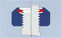
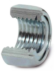
FS All-Steel Lock-Nut:
Competent reliability even under extreme pressure!
fastening
problems with dynamically highly stressed threaded joints have lead to
the development of the FS all-steel lock-nut. It has a flexible and
completely threaded locking element which is fitted into the nut body.
As opposed to competitors' lock-nuts, the FS all-steel
lock-nut can be used universally. This is due to the fact that the
design combines all elements required for a safe threaded connection,
such as re-usability, heat resistance, corrosion resistance, protection
of the counter thread and narrow tolerance of the locking torque.
The FS all-steel lock-nut can be reused many times without
significant loss of its locking capability and exceeds, after 15 times
of tightening and loosening of the nuts, the values given in DIN EN ISO
2320.
|
|
BASIC ADVANTAGES
• The FS all-steel lock-nut offers
double-safety. The locking element works both in radial and axial
direction. Thus the locking effect remains fully operational even after
repeated unfastening of the FS lock-nut.
• The FS all-steel lock-nut locking element, which is
offset but otherwise conforming to standard thread sizes, prevents the
counter thread from being damaged.
• Economical storage due to universal use.
|
|
ASSEMBLY ADVANTAGES
Cost- and space-effective automated assembly instead of castellated nuts, split pins, counter nuts, etc.
|
EXAMPLES OF APPLICATIONS:
INDUSTRIAL AREAS |
|
COMPONENTS |
ATTACHING |
1. automotive industries |
1.1 |
engine exhaust |
high temperature area of the exhaust system |
1.2 |
turbo charger |
turbo to engine manifold |
1.3 |
wind shield (bottom area) |
chassis |
1.4 |
heat shield (engine cover) |
engine compartment |
2. automotive supply industries |
2.1 |
retarder-hydraulic brake system |
installation in vehicle |
2.2 |
heat exchanger of retarder brake |
heat exchanger / hydraulic-brake |
2.3 |
servo-hydraulic pump |
secure mounting of the toothed gear on the shaft |
2.4 |
exhaust system catalytic converter |
weld nuts for repairing and replacement of components |
2.5 |
shock absorbers |
piston rod to chassis |
3. chassis and special automotive engineering applications |
3.1 |
pneumatic cushion units |
to the axle |
3.2 |
turn table of hydraulic jib trucks |
to the chassis |
3.3 |
stationary wheel-support (between turnable and axle) |
length adjustment of the wheel support |
4. process plant and machinery, building industry |
4.1 |
high-speed milling machine 18 000 rpm-shock breaked |
the milling tool and the drive shaft |
4.2 |
plate valves of reciprocating compressor |
spring steel pressure valve |
4.3 |
abrasion plate attaching (hot rolling mill) |
in areas of the furnace |
4.4 |
liquid filters (aggressive chemicals) |
filter components and inserts |
TECHNICAL ADVANTAGES
• The clamping force Is adjustable during manufacturing within fine tolerances.
• The FS all-steel lock-nut can withstand temperatures up to
1000°C. For use within temperatures in excess of 300°C, suitable heat
resistant materials are being employed depending on the application.
• High axial loads are granted as threads are manufactured to DIN EN ISO 2320 standards.
• The nut measurements meet the requirements of the standards
DIN EN ISO 7042 / DIN EN ISO 10512,
DIN 6925, DIN 980 M and DIN 6927 /
DIN EN ISO 1667 / DIN EN ISO 1664
(flange nuts).
Special designs with reduced height
are available. Please talk to our
engineers.
Flaig + Hommel is recognized, worldwide, as a manufacturer of the
FS-all-steel-locknuts and, since the 1950s, as a reliable and
innovative partner of the automotive and rolling stock industries.
BENEFITS
• Reliable even in difficult screwed connections such as used in
turbochargers, exhaust manifolds, catalysts, highly stressed gearboxes,
superchargers and vibrating machine components.
• The FS all-steel lock-nut has proven itself over many years and
has created a host of new possibilities to crack old problems (new
solutions to old problems).
• The FS All-Steel Lock-Nut are resistant to high temperatures
and corrosion due to F+H's use of modem technologies, resulting in
better reliability than galvanizing. These techniques have been
accomplished with out inducing hydrogen embrittlement.
QUALITY CONTROL CERTIFICATES
INDUSTRIAL AREAS |
|
COMPONENTS |
ATTACHING |
5. Rolling Stock Industries |
|
Railway locomotives and rolling stock equipment German Railway System Deutsche Bahn AG in BN 205 107-1 and StW 508.51.022
|
|
5.1 |
bogies |
fixing off all components (brakes, etc.) |
5.2 |
engine suspension |
on the frame (chassis) |
5.3 |
braking system |
disk brakes, brake cylinders and frames |
5.4 |
rubber/steel mounting blocks |
on the steel wheels |
5.5 |
wheel shock and noise absorber |
6. magnetic hover train
|
6.1 |
stator and rotor |
to the train |
6.2 |
|
and track |
7. lifting equipment |
7.1 |
magnetic packages (Antrieb) steering swivel (fork trucks) |
attaching and adjusting of the wheel bearings |
7.2 |
hoist equipment |
attaching of the fixing hook bolt |
8. ship and boat construction |
8.1 |
propeller |
propeller to the propeller shaft |
TECHNICAL DATA
Design ace. to:
DIN EN ISO 7042, DIN EN 1664, DIN EN 1667, DIN 980, DIN
6925 (old type) Mechanical properties: DIN EN ISO 2320 (DIN EN 20898-2/
DIN EN ISO 898-6) Surface coatings: DIN EN ISO 4042 - galvanic,
surface coatings (also Cr6-free), Delta-Tone, Zinc-Iron, Zinc-Nickel,
Hot Dip galvanized, Geomet, Delta-Protect, QPQ, Phosphate, Dacromet,
etc. |
 |
(metric) mm |
Prevailing torque (Nm) |
| |
|
|
min. |
1st
application
max. |
1st unscrewing |
15th unscrewing |
d |
h |
s |
e |
min. |
min. |
M 5 |
5 |
8 |
8,79 |
1,6 |
0,29 |
0,1 |
M 6 |
6 |
10 |
11,05 |
3,0 |
0,45 |
0,3 |
M 8 |
8 |
13 |
14,38 |
6,0 |
0,85 |
0,6 |
M10 |
10 |
16 |
17,77 |
8,0 |
1,5 |
1,0 |
M10 |
10 |
17 |
18,90 |
8,0 |
1,5 |
1,0 |
M12 |
12 |
18 |
20,03 |
12,0 |
3,0 |
2,0 |
M12 |
12 |
19 |
21,10 |
12,0 |
3,0 |
2,0 |
M14 |
14 |
21 |
23,36 |
16,0 |
4,0 |
2,5 |
M14 |
14 |
22 |
24,49 |
16,0 |
4,0 |
2,5 |
M16 |
16 |
24 |
26,75 |
25,0 |
5,0 |
3,0 |
M20 |
20 |
30 |
32,95 |
30,0 |
9,0 |
7,0 |
M22 |
22 |
32 |
35,72 |
40,0 |
11,0 |
8,0 |
M24 |
24 |
36 |
39,55 |
45,0 |
14,0 |
10,0 |
M27 |
27 |
41 |
45,63 |
50,0 |
16,0 |
12,0 |
M30 |
30 |
46 |
50,85 |
60,0 |
19,0 |
14,0 |
M36 |
36 |
55 |
60,79 |
75,0 |
30,0 |
18,0 |
M42 |
42 |
65 |
72,61 |
100,0 |
40,0 |
27,0 |
M48 |
48 |
75 |
83,91 |
130,0 |
48,0 |
30,0 |
M56 |
56 |
85 |
95,07 |
160,0 |
56,0 |
33,0 |
M64 |
64 |
95 |
106,37 |
200,0 |
68,0 |
38,0 |
|
|
(imperial) inch |
Prevailing torque (fl./lb.) |
| |
|
|
mm. |
1st
application
max. |
1st unscrewing |
15th unscrewing |
d |
h |
s |
e |
min. |
min. |
1/4 |
7/32 |
7/16 |
.488 |
3,0 |
0,3 |
0,1 |
5/16 |
17/64 |
1/2 |
.557 |
6,0 |
0,8 |
0,6 |
3/8 |
21/64 |
9/16 |
.628 |
8,0 |
1,5 |
1,0 |
7/16 |
3/8 |
11/16 |
.768 |
9,0 |
2,0 |
1,5 |
1/2 |
7/15 |
3/4 |
.840 |
12,0 |
3,0 |
2,0 |
9/16 |
31/64 |
7/8 |
.982 |
16,0 |
4,0 |
2,5 |
5/8 |
35/64 |
15/16 |
1.051 |
25,0 |
5,0 |
3,0 |
3/4 |
41/64 |
1 1/8 |
1.240 |
28,0 |
7,0 |
5,0 |
7/8 |
3/4 |
1 5/16 |
1.447 |
30,0 |
9,0 |
7,0 |
1 |
55/64 |
1 1/2 |
1.653 |
45,0 |
14,0 |
10,0 |
1 1/8 |
31/32 |
1 11/16 |
1.859 |
50,0 |
16,0 |
12,0 |
1 1/4 |
1 1/16 |
1 7/8 |
2.066 |
60,0 |
19,0 |
14,0 |
1 3/8 |
1 11/64 |
2 1/16 |
2.273 |
68,0 |
24,0 |
16,0 |
1 1/2 |
1 9/32 |
2 1/4 |
2.480 |
75,0 |
30,0 |
18,0 |
1 5/8 |
1.556 |
2 9/16 |
2.828 |
88,0 |
35,0 |
23,0 |
1 3/4 |
1.679 |
2 3/4 |
3.035 |
100,0 |
40,0 |
27,0 |
1 7/8 |
1.802 |
2 15/16 |
3.242 |
120,0 |
44,0 |
28,0 |
2 |
1.925 |
3 1/8 |
3.449 |
130,0 |
48,0 |
30,0 |
| |
|
|
|
|
|
|
| |
|
|
|
|
|
|
|
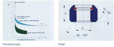
Prevailing Torques: The adjusted prevailing torques are valid for
bolts class 6g zinc plated. After the 5th loosening, the prevailing
toque remains constant. Deviations from these values may occur as a
result of different surface coatings.
Recommended tightening torques (Nm) valid for u ges. 0,12 - 0,14. |
Property class: |
8 |
10 |
12 |
Property class: Fine thread |
8 |
10 |
12 |
M 6 |
10 |
15 |
17 |
|
|
|
|
M 8 |
25 |
36 |
42 |
M 8 x 1 |
27 |
39 |
46 |
M10 |
50 |
73 |
85 |
M 10 x 1,25 |
53 |
76 |
89 |
M 12 |
86 |
127 |
160 |
M 12 x 1,5 |
92 |
132 |
154 |
M16 |
215 |
310 |
355 |
M 16 x 1,5 |
233 |
330 |
390 |
M20 |
440 |
600 |
710 |
M 20 x 1,5 |
490 |
670 |
790 |
M24 |
770 |
1060 |
1260 |
M 24 x 2 |
830 |
1160 |
1340 |
M30 |
1520 |
2100 |
2460 |
M 30 x 2 |
1670 |
2310 |
2700 |
M36 |
2640 |
3650 |
4250 |
M 36 x 3 |
2900 |
3850 |
4500 |
Remark: The recommended tightening torques are only advisory and every application must be especially calculated by an engineer.
References:

|